Cat's modified so far: 25
I recently heard about a free bar code scanner available at Radio
Shack (tm). Not one to pass up free hardware, I went and grabbed one to
play with. Not one to jump right in, I checked around on the Internet to
see what could be done with my free barcode scanner - and lo and behold,
it turns out that not only was there a linux driver, but that the author
had been sent a cease and desist order!
It seems that the manufacturer of these freebie scanners didn't like
the idea of people developing decoding software that didn't provide them
with lucrative marketing info. (Lets not even mention the serial number
that is sent everytime you scan something with this reader...)
Now, not one to give up, I kept doing research on the subject until I
found a curious note from a guy named Jeff Dobkin. It seems he poked
around on his scanner, with board revision FM+H Ver 0.3 and found that
adding a jumper caused it to output plain ASCII - and just the data, not
the serial number or type. Wow! I thought, but I have a newer rev board -
the TM+H Rev 3. Would it work? Only one way to find out - fire up the old
soldering iron.
The upside is that since it can be reasonably asserted that you own
the hardware outright, this modification is perfectly legal. You don't
need any additional software, either the original or recently released
drivers, to get useful output. It outputs plain text. This means that you
can use it in DOS apps, where the clever hacks don't seem to work so
well. Since you are messing with your own stuff, you can do what you like
to it, even solder wires onto the PCB! The downside, if you want to call
it that, is that the reader will no longer work with the supplied software
package. (boohoo... ;)
As an aside, when I get more bandwidth (which Southwestern Bell assures us
is any day now...) I will put up a mirror site as well. I have been
archiving the latest versions of code produced up till now for just such
an occasion. Hopefully, I'll get it up in time for a free threatening
legal letter - I sure would hate to miss out on that! ;)
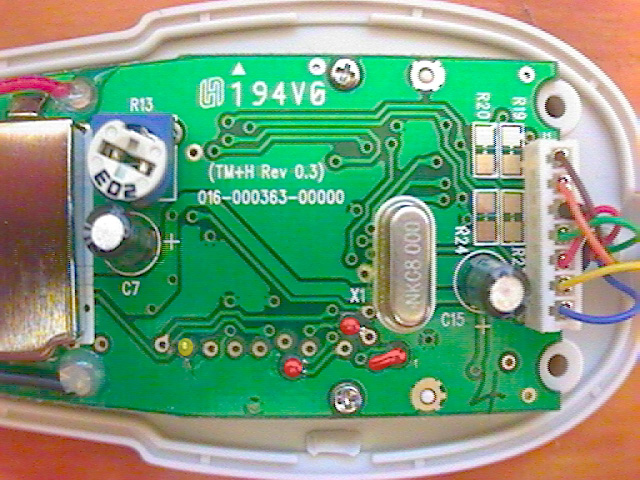
Anyway - here are some illustrations showing how to perform the
modification on your scanner. Shown below are some pictures of my
scanners board, with colored dots noting areas of interest.
This second image shows the backside of the board with the jumper
wire.
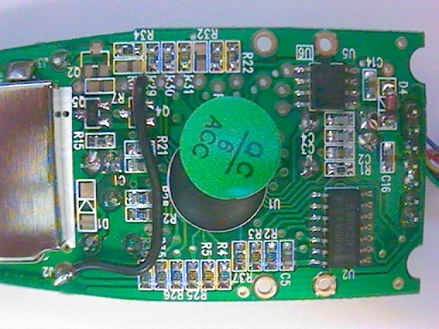
The yellow dot covers the
pad that you should jumper to. You need to apply +5 volts to this pad, so
jumper a wire from the RED LED power wire (Vled+) to this pad. Jumpering
to other pads doesn't seem to have any effect on the scanner, but also
doesn't harm the scanner either. As a side note, I suggest you "tin" the
wire before inserting it into the plated hole. Tinning just means heating
the wire and letting it soak up a little solder until it looks like a
solid wire. Don't use too much solder, though, or it won't fit in the
hole.
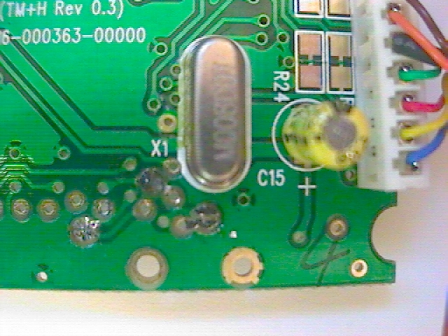
Lastly, it is possible to disable the serial number
embedded in each scanner as well. If you will notice the red shaded pads
near X1 - you will discover that they connect a certain serial EEPROM
chip, a S93C46DV03. By removing the shorting "blobs", you will disconnect
the serial EEPROM from the microcontroller, effectively declawing the
board. Note, if you apply the above hack, there isn't any point in
applying this one, as the serial number data isn't sent. If, however, you
want to "anonymize" your cat, then by all means - desolder those
connections!
As a side note, I have read that you can still use a
reader with the serial EEPROM disabled with the original software. By
only applying this second modification, you get a reader with no
serial number at all.
Here is a closeup showing the pads that
should be desoldered. Use a find desoldering braid, available at any
decent electronics store, to remove the blobs
Note, none of the
info on this page was original thought. The text clipping I made indicates
a certain Jeff Dobkin found out about this first. I found the reference at
http://www.topica.com/lists/pla_upl/read/message.html?mid=1702776249
I would like to note Michael Guslick's excellent hardware discussion at
http://air-soldier.com/~cuecat/.
From this site, I understood the importance of the serial EEPROM
chip. Desoldering these pads was merely an extension of this. :)
Obviously, I don't need the driver software anymore, but I did go to the
trouble of understanding how the encoding scheme works - and it is
terribly simple. (laughable, if this was the basis for any kind of legal
protection). There is a great site http://www.fluent-access.com/wtpapers/cuecat/
kept by Stephen Satchell regarding the encoding scheme.
So, now where? Well, you have a fully generally purpose barcode reader -
you do the math. Personally, I'm whipping up an Access database based on
both the modified, and unmodified readers. The unmodified reader can be
used to provide accountability - see who changed that data by storing the
serial number along with the data!
Good luck!
UPDATE 10/3/2000 (1)
Apparently, the decryption on/off switch is different for different
boards. The FM+H Ver 0.3 and TM+H Ver 0.3 both appear to use the second
pad from the left. The HO+E Ver 0.2 board uses the *FOURTH* pad from the
left. This corresponds to a scanner model 05A00 - the 07A00 all appear to
use the TM+H Ver 0.3 boards.
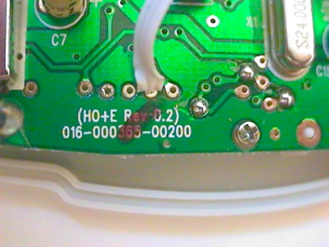
Here is a picture of the HO+E board
with a jumper wire inserted. The purple mark points to the correct hole
(though this may not be true on your board!)
UPDATE 10/3/2000 (2)
Well, wouldn't you know it - the engineers that developed this thing had a
few things up their sleeves. For most barcodes, the wand just spits out
the data. However, type 128 barcodes, which the original cues are
based on, produce something else:
a5 61 62 a0 52 35 43 98
6162TCK
The lower line is the actual barcode data. The upper line is junk (as near
as I can tell). If someone knows the significance of this data - please,
let me know! It doesn't appear in the coded version, though, so my guess
is that it is diagnostic data. Well, you can't have it all... Fortunately,
much progress is being made on software drivers. :)
In the meantime, the wand works just fine in this mode for every other
kind of barcode type the reader is capable of reading.
Update 10/4/2000
It appears that a pattern is forming - boards whose revision code starts
with a T use the 2nd pad from the left, while boards with a revision code
starting with H use the 4th pad. Regardless, the appropriate pin is wired
to resistor R29. (Thanks to Chad Fawcett for this hint)
| Board Revision | Hack works? | Pin to jumper |
| FM+H Rev 0.3 | Yes | 2 |
| TO+E Rev 2.1 | Yes | 2 |
| TM+H Rev 0.3 | Yes | 2 |
| HO+E Rev 0.3 | Yes | 4 |
| HW+H Rev 2.1 | Yes | 4 |
| HM+H Rev 1.1 | Yes | 4 |
If you have a board not mentioned in the table above, please give the
hack a try, and indicate if it worked or not. It would be nice to see how
many board revisions are out "in the wild".
(C) Seth Henry 2000 All rights reserved.